
GoPro Hero 3 plus (and others?) A/V out fix (USB broken)
The USB socket problem
It turns out that the GoPro’s USB socket is very fragile, specially on the GoPro 3, 3+ and 4. There’s plenty of reports from broken sockets even during normal use. GoPro will however not honor warranty for these.
Having the socket broken is not the end of the world as the camera still works otherwise fine, but you need an external battery charger and of course to take the sdcard out when you copy stuff on it - and GoPro updates may not necessarily work.
I also use mine to transmit video live in analog mode (the USB socket can output audio/video in analog).
The “fix”
One solution to this problem is to purchase a 10-pin female mini USB socket and solder it in place (since your original socket pins will most likely be all destroyed).
The pads are about 0.5mm and without expensive, specialized equipement this can be a pain.
One way to do this is to position the USB socket on the pins, then heat up all pins at once. Unfortunately this may often end up in melting the plastic inside of the USB socket.. and then you’re back to square one.
Another solution is to find exposed contacts that are larger than the pads. Sadly for many of the pads these are hard to find.
The solution I used is a mix of that and mix of soldering small wires directly to the pads. That’s what I ended up doing.
Materials
- Fine soldering iron tip (1mm in my case - smaller is generally on really expensive irons): iron tip
- Fine teflon wire
- Some tape (if possible electric tape or high temperature tape).
- Some thicker wiring (like 20 or 24AWG) and plugs depending on what you want to do.
- Probably some magnifier
- A bunch of small screw drivers.
- Probably some alcohol to steady the hands.
Do it (tm)
Start by dissassembling the GoPro, there’s a few guides:
Remove the USB socket, if its not completely broken off the pads, heat them up and remove it. Careful! There might be some other component that broke as the USB socket pushes against them. You might need to resolder these but it’s quite easy.
The teflon wire goes onto the pads obviously. With the USB socket on the top, the 10 PINs are assigned as follow:
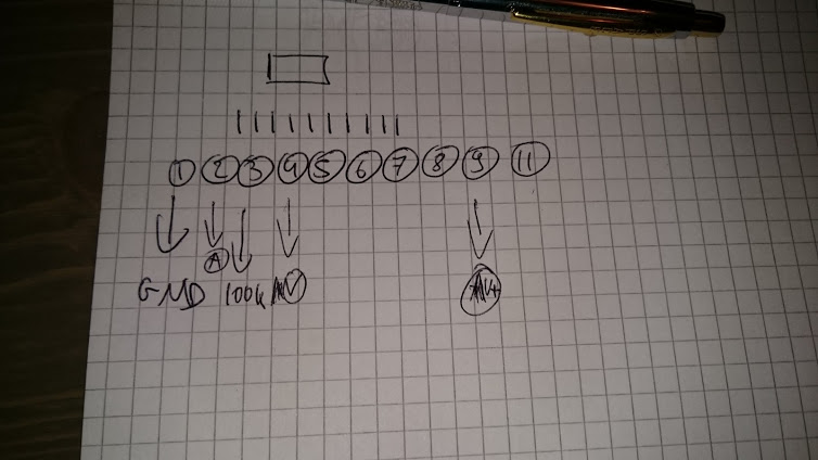
I soldered a 100k resistor between the ground and PIN 3 in order to enable video out. I also soldered a wire to PIN 4 to get the actual video out. Finally (not pictured) I soldered a wire to the ground (not the ground PIN, since you don’t need to and its easier to solder elsewhere).
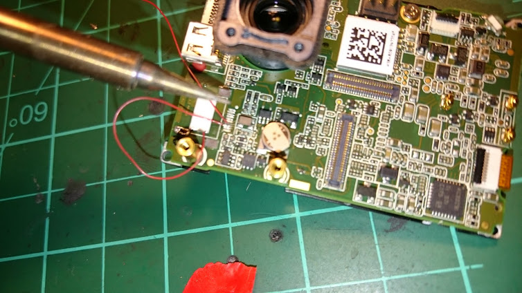
Make sure you tape the whole thing so that wires don’t move especially if you let them go through the USB port.

Yay it works.
Comments