
Ritewing Zephyr build log
Once upon a time, little kang decided to make a flying wing.
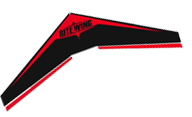
Flying wings are cool he though, they look different, are easier to transport, robust and fun!
In his search for a good flying wing, at the time, only one would fit: the Ritewing Zephyr.
This wing is available on special demand only, it’s 1.4 meter wide and approx 80 centimeters wide total (not the wing portion width but the aircraft complete width), 1kg to 2.4kg and delta shaped. It uses a low drag airfoil, thus flies fast, even if the said airfoil is thicker than many other wings.
The thick airfoil allows easier storage of the FPV gear (more space inside), and broader flight speed range.
Now, that’s a kit, and far from ready to fly. Besides, one is free to choose how to build it, what to make out of it and so on.
My plan was simple:
- I like as light as possible.
- I need it to fold into 2 pieces for transportation (and not 3 or more).
- I need it strong enough to resist long transport inter-countries, and some crashes (yeh, I crash.).
- It needs to fly a while, 20 or 30min.
The materials
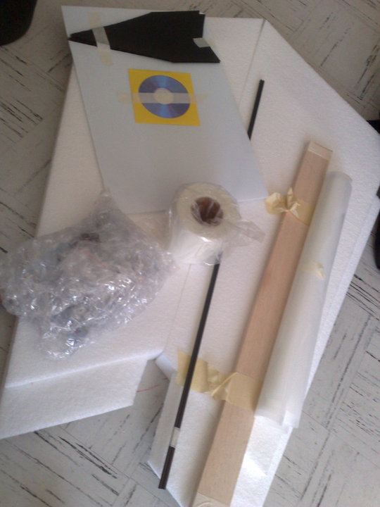
- Ritewing Zephyr wing cores (it includes 4 thin fiber glass spars and 2 big. fiber glass spars, sometimes carbon, as well as a coroplast sheet and 2. coroplast winglets, 2 balsa elevons, motor mount(s)).
- Riteweave fiber glass, or any light fiber glass tissue.
- Laminate covering film (Ritewing can provide that on demand).
- 2 cans of 3M90 spraying glue (and no other!).
- Some UHU POR or equivalent foam safe, flexible glue (stays flexible when dry).
- Some foam safe CA + accelerator.
- Some fast, very strong, 2 components epoxy (5 min epoxy is fine).
- Eventually Gorilla glue.
- Fiber glass tubes (why fiber glass? because it’s nearly as strong as carbon,
but it’s more flexible, it flexes instead of breaking on effort. Also, it let
radio-waves through). Note that sizes don’t have to be exact, and we’ll cut
proper length. But one fiber tube needs to be 1mm bigger than the internal
other tube size, as we will make it go through it..
- 6x4x1000mm x1(external size, internal size, length) or more depending on what Ritewing provided (carbon or fiber), if you’re not sure get 3x.
- 8x7x1000mm x1.
- 4x2x1000mm x1.
- 4 nylon screws of a decent size, around 5 or 6mm wide.
- 4 nuts for the nylon screws.
- A pair of gold’n’rod push rods (or any strong, high quality rods).
- A pair of 4.2kg digital servos (I use
HGD digital 250 MetalGear
<http://www.hobbyking.com/hobbyking/store/uh_viewItem.asp?idProduct=5192>
_ from HobbyKing). - A pair of 2250mah (25C Rhino for me, but others will do too) battery packs.
- A hacker A30 motor + X40 ESC (again, you might want some cheaper Turnigy equivalent).
- 3M Packaging clear tape (and no other!).
- Some thin plywood.
- Strong velcro for equipment bays.
- Some dean plugs (or any power plug of your choice), thin servo wire, large battery wire, various shrink warp sizes.
- A bunch of servo plugs male and female (10+).
- Fresh hobbyknifes/cutter/xacto, whatever you like best, but have a few brand new blades that’s the most important.
- Some kind of small drill.
- Metal saw.
The build
Preparation
Note: First of all, please note that it is highly suggested to read other, regular Zephyr build logs. I will not go into deep details for regular things such as servo holes, re-cutting the elevons or such things, but try to keep it simple and clear for the most important points.
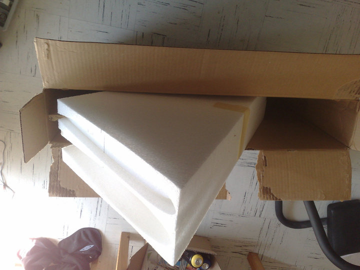
Get the wings out and keep the bottom wing bed. They protect the wings as you work on them. You can figure what is the top either by markings on the EPP, or because the bottom of the wing is more straight and plane than the top.
You can keep the top ones somewhere else, as scratch EPP to test stuff.
Verify that both wings are in good condition and proper shape. Otherwise you can correct them with some heat, flex, and leaving them with books on top for a few days… Generally they come out quite perfect anyway.
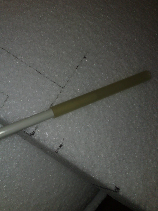
2 holes for the spars should be pre-cut. Check your spars (included by Ritewing) fit into them and are the right length, and that they also fit into your wide fiber glass tube. If not, use your own smaller tube (the one that slide into the bigger tube… clear?! :P)
Wings assembly and folding mechanism
Drill a 3rd hole near the front of the wing, for a 3rd spar. Be careful to drill straight and not too far into the foam. EPP is not so brittle but it’s not possible to make a perfect drill either. That’s ok. If you’re lucky, you may have a hot tube to make a perfect hole instead.
Eventually, you may ask Ritewing to add this hole for you before you order.
The 3 spars installed. Note the position of the front 3rd spar. Note the motor mount drawing which is going on top of the rear spar.
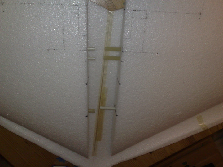
Measure the spars to be installed as on the picture above. The dark tubes are the outer big tubes.
Important: On both sides, we’re using the same inner spars. But only one side has an outer (big, dark) tube on top, only on the last part of the spar. Make sure to leave enough space for the front batteries and the camera before you place your third spar. (Read on for batteries location).
Outer tubes are approximately 10 cm long. The exact size is unimportant, they should just slide a good bit into the wing and have a few centimeters showing outside the wing, as on the picture. The inner tube should not slide completely into them so that the other side’s tube has space to slide.
It’s important that the outer tube sticks OUT of the wing, while it makes installation a bit more complicated, it adds a lot of strength in the center of the wing, this is the weakest area of the wing and thus the most important.
In ascii
-------- inner spar
=== outter spar
Assembled
Left spar              Right spar (slides into left spar)
---------------====    --------------------
Clear enough?
I suggest you tape the part of the tube you’re going to cut before cutting, it avoids having part of the fiber breaking away. I’m using a metal saw for the cut.
Test fit your spars and get a good idea of each tube’s position. When satisfied, sand the inner tubes a bit, so that the glue rips better.
Glue the inner tubes to the outer tube with the epoxy (be gentle, don’t put too much). Test fit again, make corrections before the glue is dry, but don’t leave spars in position or they might glue to each other.
When it’s all dry and perfect, you can glue the tubes inside the wings. For this, you may use the Gorilla glue (or the UHU+CA if you prefer or don’t have Gorilla, the later is the strongest):
- Hold the wing vertically.
- Drop approx 10 drops of Gorilla glue inside the spar’s hole - you don’t need to put too much Gorilla glue. Try not to put glue at the first few centimeters of the spar hole on the side with the thin inner spar only (it’s ok on the side with the outer spar).
- Use a water spray (I use a used window spray filled with water) and give 2 or 3 push of water into the hole. Gorilla glue activates with water..
- Put the spar in and slide it a few times, to spread the glue.
- Eventually, add a little more glue near the start of the hole on the side which has the outer/big tube. NOT on the other side!.
- On the side which has the thin inner spar, use some spare outer tube to clean off any glue around the first few centimeters, so that the outer spar of the other side slides properly..
- Test fit, then disassemble (or it would glue spars together!) and let dry a few hours.
- When dried, some Gorilla glue might be escaping outside of the EPP, just cut it out with a new, clean blade.
Wing and motor mount cuts
Referring to the above picture once again (the wing tubes), we need to cut the wing and place the motor mount.
The picture, below this time, should give you an idea of the shape of the wing after the cut on the bottom:
While assembled, trace your cut with a pen and a ruler. Depending how much weight will be in the nose, you might want to cut a little deeper (to bring the center of gravity forward) - check your center of gravity quickly by fitting your elements (batteries, etc) before-hand. It doesn’t have to be precise, as we will adjust later on, but should not be completely off either.
The less weight in the nose, the deeper your should cut (without going too far obviously, don’t exaggerate). Having 2x 2250mah batteries of 175gr each and very light HD camera (~25gr), I use these dimensions (GoPro users or bigger batteries probably need the motor to be less frontwards):
- Front spar: 14cm from the tip
- Battery bays: 1.5 to 2.5cm from inner wing. 1.5cm from wing tip (along the edge)
- Propeller clearance: 14.5cm on each side (starting from the inner wing edge, not the motor mount edge)
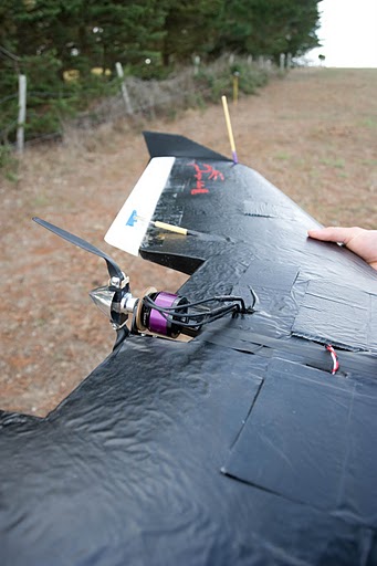
A little blurry sorry.. this wing also survived a zillion crashes hence the paint damage hehe.
The motor mount cut goes on top of the bottom spar, for strength. The spar also resonate with the motor’s vibrations as a side effect which makes a very typical “Ritewing” noise - yes it’s noisy ;)
To draw the motor mount, you can simply place it on the wing and trace the edges. Don’t cut the whole motor mount you’ve traced out of the EPP! You only need to cut the inner “U” (you will slice an insert for the mount in the EPP afterwards), you need some EPP to support your mount on the other parts of the EPP :P
The cut is done using a brand new blade, this is important, or the EPP won’t cut cleanly and your wing will look bad and perform less good.
Motor mount details
The mount is cut into 2 parts using a metal saw. It is slightly sanded to avoid cutting your skin.
Start by reinforcing the mount by adding some plywood on the arms (don’t cover the screw holes. Glue it with the epoxy.
You need to cut open in the middle of the EPP’s motor mount position, using a brand new blade again (it can be the one you’ve just used tho), so that you can slide the motor mount inside the wing, on both sides.
Test fit the motor mount, the thrust line should be right in the middle. When you’re satisfied, glue the mount in place on both side using epoxy. Before it dries, make sure it fits properly, this is very important. The other part of the motor mount (black U) should of course fit perfectly on the aluminum motor mount or it will vibrate and damage your wing, motor, etc and fly poorly. Newer Zephyr might ship with a stronger mount than the black U (which is from Hobby King) but the process is identical.
Check that you can mount the motor on top of it and that the propeller is going to be exactly parallel to the wing - be quick, epoxy dries in a few minutes. When you’re satisfied, let the epoxy dry for at least 10 min.
Equipment bays
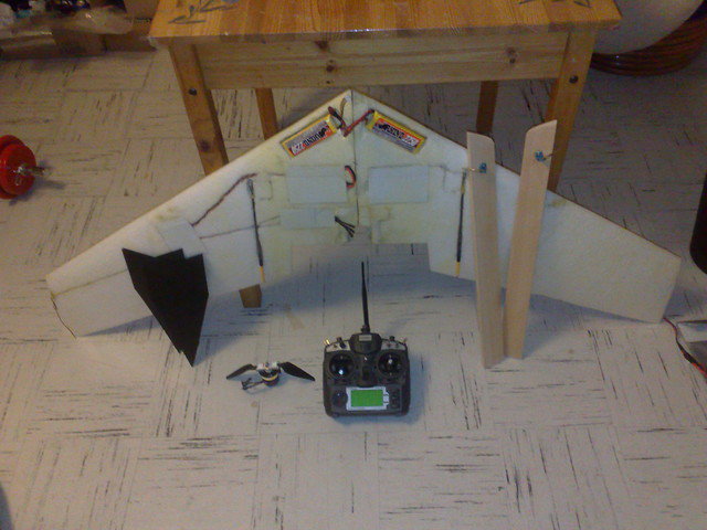
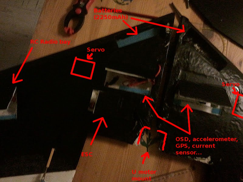
Wings assembled, mount all your equipment including the motor on the wing. Tape stuff so it doesn’t falls off, and try to find your favorite placement. Check that the center of gravity is around 11 inches from the tip of the wing, or 26.5 cm, approximately.
You will need to have most of the equipment pretty much forward, so servos will be rather high, and the batteries are in “V” at the tip of the wing as you can see on the picture once again.
See the previous picture again to get an idea where to place your equipment, and how. You may refer to traditional build log to cut these, I cut mine with a hot soldering iron and a big screw in place of the iron tip. There are better ways, but it works just as well. The bays are covered by coroplast doors which close with strong velcro.
The batteries are fixed with velcro and have no coroplast over them, in case of crash they just pop straight out and disconnect if the wing separates.
There is a thin carbon tube inserted in front of the battery. As you can see, my batteries are very much forward in comparison with regular builds. This allows me to get more space for the rest of the equipment.
The carbon-strengthened tip is extremely strong and not brittle at all.
In general, servo wires will be long enough so they can be connected once the wing is assembled.
Winglets details
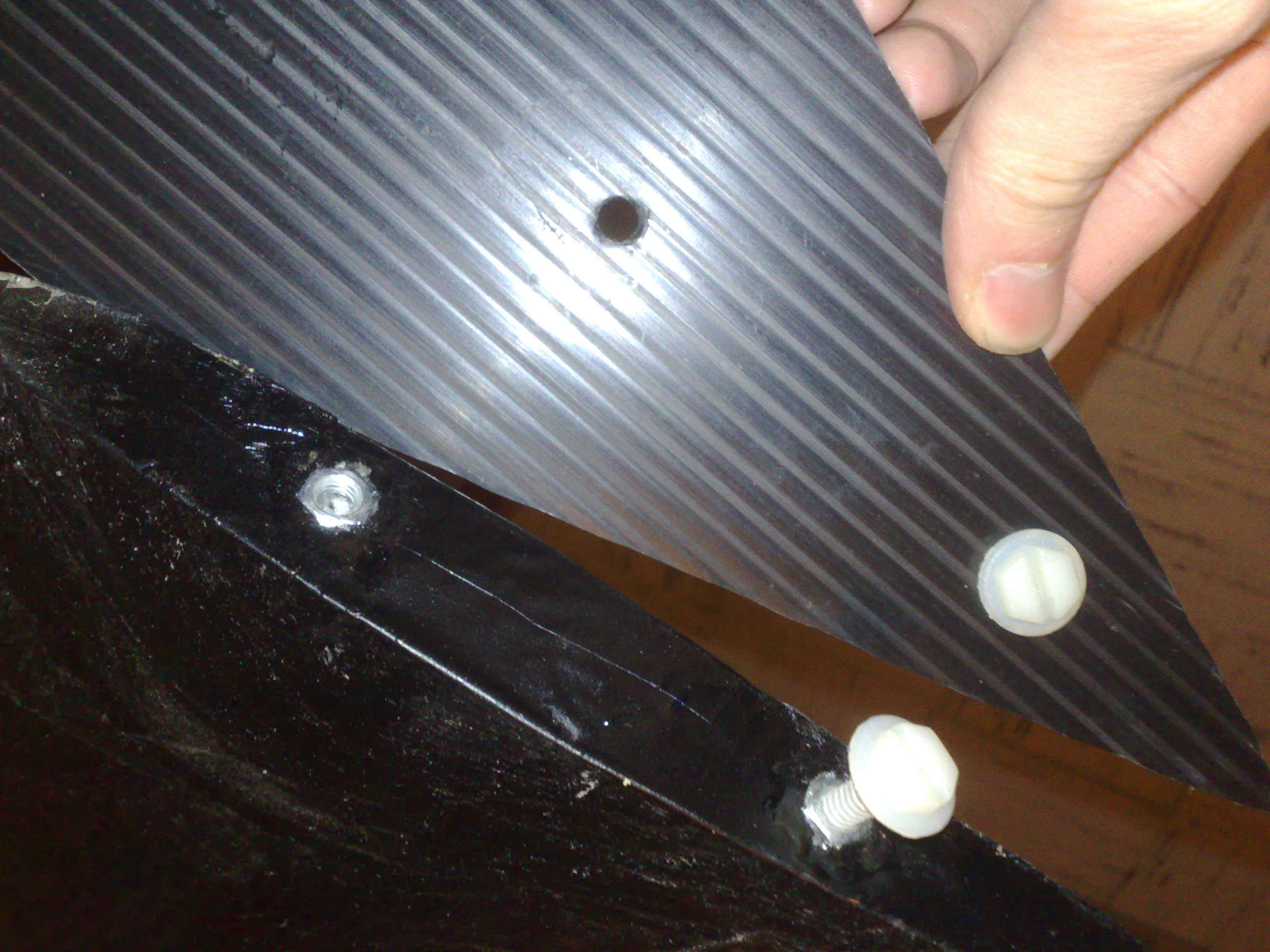
The winglets are fixed using 2 nylon screws on the side of the wings. You can judge the best place for these easily and the measure don’t need to be perfect, just make sure that you test fit them before drilling holes.
I drilled 2 holes in each winglet, and drilled just a little bit the corresponding holes in the wings sides.
Inside the wing in each hole we drilled, we place a nut. The nut must be tight, so do not over-drill it (the hole should be a bit deeper for the screw to fit in however).
The nut is glued with the epoxy 5min, make sure to clean up the excess of glue so that the screw can still, well, screw itself inside the nut properly.
Test fit, test screw, it should be smooth and easy, yet strong enough to resist most crashes. If your nylon is weak enough (mine is a bit too strong, but it’s hard to find the right screws sometimes), the screw will break before the nut is ripped off the EPP. If the nut ever rips off the EPP it’s however easy to glue it back in.
Covering
The inner part of the wings are covered using the fiberglass tissue. First, 3M90 is applied, then the fiberglass is placed, then more 3M90 is applied, like with a regular build. The coverage includes the battery bays, inner central wing section (make sure its very plane there) and top/bottom of the central wing section.
Looking at the “close to finished” picture you’ve seen earlier, the yellowish section is the section to be completely glassed, as described. Let this dry a day or two if necessary.
Once this is done, you may choose the paint your wing (the regular Ritewing way, again), or simply cover it with the laminating film. I did the latter.
A thin layer of 3M90 is spread on the wing, and large parts of laminating film are cut and applied with an iron at quite high temperature. Again, refer to the regular Ritewing way.
Make sure your wing stays plane during the process and do not over-heat the EPP or it will flex and destroy your airfoil.
Once finished, I painted over the lam film using strong spray paint (do not use silver or such colors as they contain metal and will interfere with the radio signals). This is the kind of spray people use to spray walls and tag - it’s very strong. The finish is excellent (better than other wings) and the paint rarely goes off on crash. It’s also water resistant.
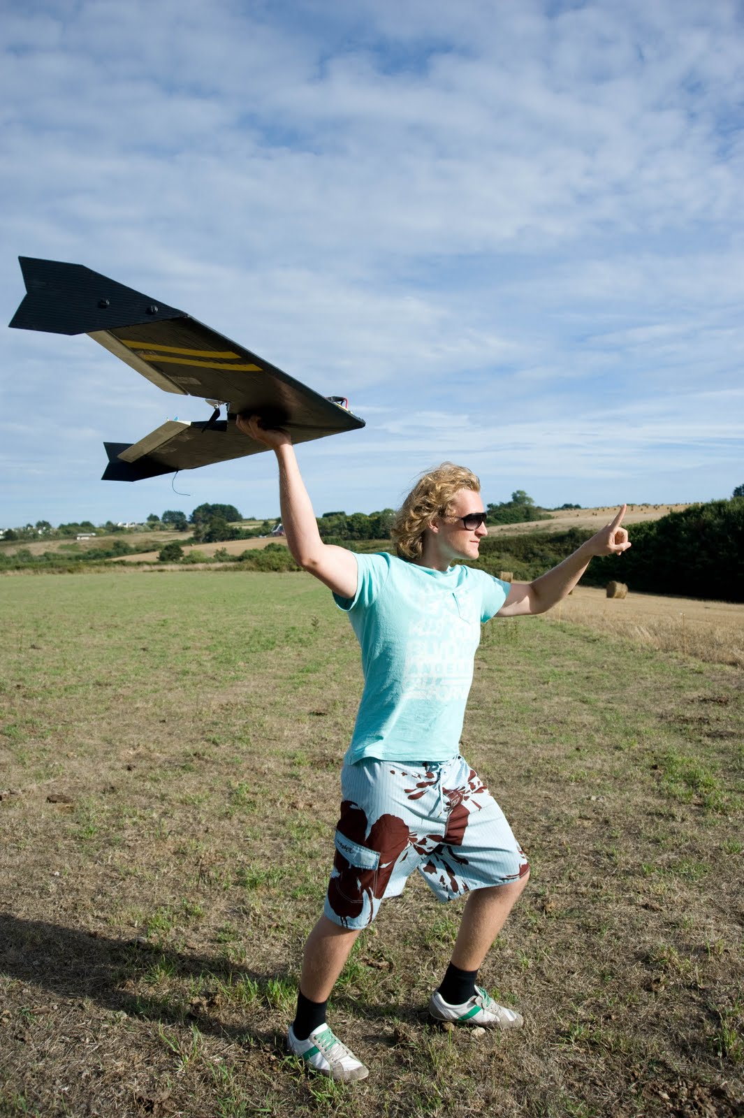
The above picture shows the completely Zephyr before a flight on a French island. The wrinkles are due to the fact that the iron was not hot enough, it still look pretty good however. The FPV equipment I use is so light that it’s barely visible. The antenna here is the RC antenna.
The front camera is slightly visible on the top of next picture.
Remaining FPV equipment
The video transmitter is tapped to the right wing side (opposite of the RC radio link).
The camera is a very lightweight HD camera (Camileo P10, board only) and is taped in between the wings. For a more conventional setup, just cut a hole for a servo (pan) on one of the wings for example, the camera does not have to be in the center of the wing.
Enjoy !
If you have any further questions, feel free to ask, I’ll try to complete it.
Comments